CARBON PROPELLERS for DRONES & UAV
E-PROPS : Conception - Essais - Inertie Hélice
Le bureau d'études E-PROPS est composé à ce jour de 18 ingénieurs et techniciens aéronautiques.
Ils réalisent les calculs théoriques, la modélisation, la mise au point des prototypes, puis les expérimentations au banc au sol et en vol. Ils ont une grande expérience, reconnue par leurs pairs, et sont sollicités régulièrement pour intervenir lors de conférences et colloques spécialisés.
Quelques informations sur les travaux du bureau d'études E-PROPS :
1 - Conception / Design hélices
2 - Méthode d'optimisation d'hélices aéronautiques
3 - Hélices de 3ème génération
4 - E-PROPS : essais sol
5 - Bancs d'essais
6 - Propulsion : un peu de théorie
7 - Hélice et Moment d'Inertie
8 - Influence de l'inertie hélice
- les caractéristiques du moteur thermique ou électrique (puissance, couple, régimes)
- l'appareil qui va être équipé avec ce groupe motopropulseur optimisé : configuration tractive ou propulsive, caractéristiques aérodynamiques, interactions ailes / fuselage...
- les performances souhaitées de l'appareil
- les conditions d'utilisation de l'appareil et de son groupe motopropulseur
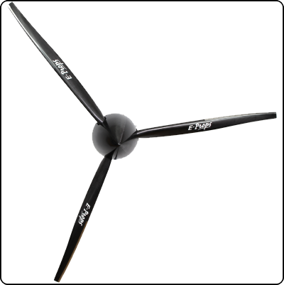
Les hélices E-PROPS sont étudiées pour être les plus légères possibles, très solides, permettant d'obtenir un excellent rendement et en tentant de générer peu de nuisances sonores.
- la cellule et le moteur étant fixés, la vitesse de vol, le régime de rotation et la puissance sont imposés;
- le diamètre est souvent restreint par la géométrie de l’appareil. Et si par chance il ne l’est pas, c’est la vitesse périphérique et les problèmes supersoniques qui vont limiter le diamètre.
Le diamètre et la puissance du moteur fixent le rendement propulsif, c'est-à-dire la limite supérieure absolue du rendement possible de l’hélice. Ensuite, c'est au concepteur de l'hélice de se rapprocher de ce rendement.
Comme paramètres d’optimisation, il reste donc :
- le nombre de pales
- la répartition de traction sur l’envergure de la pale
- la répartition de corde
- la répartition de pas
- l’évolution de profils
Augmenter le nombre de pales permet de réduire la portance de chaque pale, et donc de réduire la traînée induite de chaque pale. Mais à corde constante, cela augmente la traînée de frottement. Et si l’on réduit la corde, la chute des Reynolds dégrade l’aérodynamique des profils, sans compter les problèmes de tenue mécanique.
La recherche d’une répartition de traction optimum doit prendre en compte les effets de celle-ci sur la traînée induite des pales. En effet, le saumon ne peut pas générer une forte portance sans causer une énorme traînée induite.
L’optimisation en corde cherche à ce que chaque profil travaille à finesse maximum, sans négliger les effets de la variation des Reynolds, et en vérifiant l’adaptation des profils à leurs conditions de fonctionnement en CZ, en Reynolds et en Mach.
La répartition de pas sert de variable d’ajustement pour maintenir chaque profil à son coefficient de portance optimum en vue d’obtenir la répartition de traction choisie avec une répartition de corde et de profil optimisée.
De par sa complexité, la conception d’une hélice est un procédé itératif : chaque modification influe sur les autres paramètres.
Depuis les débuts de l'aviation, les hélices n'ont pas cessé d'évoluer.
On distingue à ce jour trois périodes principales :
Les gains de performances sont importants. Ces hélices dites "de 3ème génération" (comme les E-PROPS) remplacent peu à peu toutes les hélices d'ancienne génération, ce qui permet d'accroître les performances et la sécurité.
Les constantes avancées des technologies, des outils de conception et de tests laissent envisager dans les prochaines années de nouveaux progrès sur cet équipement essentiel de l'aéronef qu'est l'hélice.
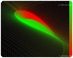
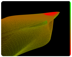
Des essais ont également été menés en soufflerie, lors de développements d'E-PROPS spécifiques pour les drones. Ces essais sont confidentiels et ne peuvent pas faire l'objet de communications. Ils ont permis de vérifier de nombreuses hypothèses et d'enrichir le logiciel LUKY.
Exemple :
VIDEO : Campagne d'essais : hélices E-PROPS à pas réglable pour moteurs de 50 à 115 kW
Campagne d'essais : hélices E-PROPS à pas réglable pour moteurs de 50 à 115 kW. Tests de traction, flexion et torsion.
Des pièces carbone aussi solides que l'arbre du réducteur Rotax !
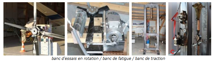
- Banc d'essais instrumenté hélices pour tests en fonctionnement, avec système de mesure de traction. Un moteur électrique permet de faire des essais comparatifs de bruit d'hélices.
- Banc d'essais en fatigue. Ce banc permet de solliciter l'hélice en carbone par flexion alternée, pour reproduire le couple moteur et ainsi démontrer un potentiel vérifié de l'ensemble moyeu - pale.
- Banc d'essais de traction mécanique : vérin hydraulique 40 tonnes pour les essais de traction et de compression des pales et des moyeux. Ensemble instrumenté pour enregistrement des données.
En 2015, l'équipe E-PROPS a acheté un ULM SKYRANGER équipé d’un Rotax 912S 100 cv.
Cet investissement a été réalisé pour poursuivre le développement de la gamme d’hélices pour ULM / Avions.
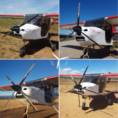
Cet appareil possède une structure "tubes et toile" très simple, qui facilité le montage d'instruments innovants d’enregistrement des paramètres de l'hélice dans toutes les phases de vol.
Le DAU (Data Acquisition System) appelé MERLIN, conçu et fabriqué par le bureau d'études E-PROPS, permet d'obtenir de nombreux paramètres à chaque instant du vol : traction hélice, couple hélice, T°, pressions statique et dynamique, régime moteur, pression et T° d'admission, valeurs d'incidence et de dérapage, etc.
Un système complexe de différents types de capteurs et jauges de contraintes est intégré dans le moyeu de l'hélice, sur les pieds de pale, ainsi qu'à différents endroits stratégiques de l'aéronef. Pendant le vol, des milliers de mesures sont envoyées en temps réel par liaison Bluetooth à un ordinateur situé dans l'appareil, ainsi qu'à un afficheur qui permet au pilote d'affiner son pilotage en fonction des paramètres demandés et obtenus.
Les résultats obtenus sont plus précis et proches de la réalité que des essais en soufflerie, et ils sont obtenus dans un temps très court (le temps du vol). Pour obtenir le même nombre de données, il faudrait des années de campagnes d'essais dans des souffleries. En outre, rien ne remplace les conditions réelles de vol.
Les données sont ensuite intégrées au logiciel LUKY .
Cet ensemble de moyens d'essais et d'analyse (ULM + DAU + logiciel) apporte une aide novatrice et précieuse aux ingénieurs du bureau d'études E-PROPS.
Tout d'abord, la troisième loi de Newton (ou principe des actions réciproques) indique que :
"Tout corps A exerçant une force sur un corps B subit une force d'intensité égale, de même direction mais de sens opposé, exercée par le corps B".
Cette loi se résume par le principe : " Action = Réaction".
Ceci signifie que si l’on souhaite que notre hélice "A" profite d’une force vers l’avant, il va falloir qu’en retour elle applique sur "B" une force vers l’arrière. Dans le cas de la propulsion aérienne, il n’y a qu’un "B" possible : c'est l’air traversant le disque balayé par les pales.
Il s’agit en fait non d’une masse proprement dite, mais d’un débit massique, produit de la surface du disque d’hélice, de la vitesse et du flux et de la masse volumique.
Pour appliquer une force sur le débit massique d’air, les pales se comportent comme des ailes. Leur profil aérodynamique leur permet d’appliquer des efforts de portance sur le flux d’air. L’hélice applique donc une force sur un flux d’air, ce qui a pour conséquent de modifier la vitesse du flux d’air.
La différence de vitesse entre l’amont de l’hélice et l’aval se calcule ainsi :
Différence Vitesse (amont/aval) = Traction / Débit Massique
DV = T / dm
Équation issue de la 2ème Loi de Newton F = d(m.v)/dt
Cette variation de vitesse induite par la traction s’applique pour moitié en amont de l’hélice et pour moitié en aval (comme le démontre la relation de Froude).
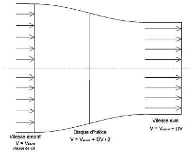
Le débit massique du flux d’air dans lequel travaille l’hélice est donc : Dm = mvo x Sdisque x (Vvol + DV/2)
Où :
- mvo = masse volumique du fluide (kg/m^3)
- Sdisque = surface du disque balayer par l’hélice (m²)
- Vvol = vitesse de vol
On a donc un système d’équation permettant de calculer la différence entre la vitesse en amont de l’hélice et la vitesse en aval, ainsi que le débit massique. Si l’on fait quelques calculs de puissance autour du fonctionnement de notre hélice, on obtient :
- La puissance utile fournie par l’hélice à l’avion : Pu = Traction x Vvol
- La puissance absorbée par le phénomène propulsif : Pa = Traction x (Vvol + DV/2)
Ce qui donne le rendement propulsif : rp = Pu / Pa
=> Le rendement propulsif fixe une limite absolue vers laquelle toute conception d’hélice devrait tendre
Comme le rendement propulsif fixe la limite supérieure de rendement d’une hélice, le choix d'une hélice de petit diamètre par le concepteur d’un aéronef aboutira à de piètres performances. Ceci est d'autant plus vrai que la vitesse de vol sera faible.
Si le nombre de pales peut permettre de réduire la perte de performance (nous verrons comment un peu plus loin), cela ne permet en aucun cas de retrouver les performances d’un diamètre adapté.
Si le concepteur d’hélices ne peut pas outrepasser les pertes liées au phénomène propulsif, il doit cependant ne pas les dégrader par une mauvaise répartition de la traction sur le disque d’hélice. Et doit donc choisir une répartition de pas, de corde et de profil permettant une répartition de charge optimum.
Malheureusement, il existe d’autres sources de perte énergétique : les pertes liées à la traînée des pales.
En effet, les pales se comportent comme des ailes et génèrent portance et traînée. Cette traînée se décompose en deux parties : la traînée de frottement et la traînée induite par la portance.
Traînée = 0.5 x mvo x S x CX x V²
Le cas de la pale est plus complexe que celui de l’aile, car la vitesse est variable :
- au pied de pale :
Vitesse faible et corde petite donnent un nombre de Reynolds ridicule dégradant beaucoup les caractéristiques du profil (CX important et CZ max faible).
- en bout de pale :
Vitesse très grande et corde très petite, le nombre de Reynolds reste petit.
Mais la vitesse étant proche de celle du son, le nombre de Mach est important.
Le Mach important dégrade les caractéristiques du profil. Un petit défaut de courbure, d’incidence, et une zone d’écoulement risque de passer supersonique, générant du bruit et dégradant les performances.
La modélisation de cette traînée induite est délicate, car, contrairement au cas de l’aile, la vitesse est variable le long de la pale.
Pour ce point précis, les chercheurs d'E-PROPS n'ont pas trouvé pas de méthode satisfaisante dans les publications spécialisées ni auprès de laboratoires. L’équipe a donc développé une méthode de calcul originale et efficace, mais un peu gourmande en calcul. Les calculs itératifs de définition des effets induits pour les pales représentent 90% du temps de calcul nécessaire à la modélisation complète de l’écoulement.
Nous avons vu ici en quelques mots quelles étaient les causes de perte énergétique de la propulsion par hélice, sans toutefois entrer dans les détails trigonométriques de la chose : ces détails ne représentent un réel intérêt que pour l’hélicier.
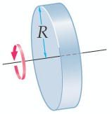
Pour des objets en rotation, la masse n’est pas une donnée suffisante. On a associé la masse de l’objet à sa distance par rapport à l’axe de rotation afin de pouvoir comparer la capacité de résistance à une variation de vitesse angulaire. Il s’agit du moment d’inertie, qui se mesure en kg.cm²
Le moment d'inertie est une donnée très importante pour les hélices.
En effet, les moteurs aéronautiques sont le plus souvent des moteurs à pistons. Le vilebrequin subit une poussée de la bielle à chaque tour en 2 temps, et tous les deux tours en 4 temps. Le vilebrequin est accéléré pendant un demi-tour, et est freiné pendant le reste du cycle. C’est l’inertie de tout l’ensemble rotatif qui va permettre d'assurer la remontée des pistons et la régularisation de la rotation.
L’hélice constitue le plus gros volant d’inertie. Si elle est entraînée par un réducteur (pour les moteurs réductés), les pointes de couple moteur seront encaissées par le réducteur. Si elle est reliée directement sur le vilebrequin (pour les moteurs en prise directe), celui-ci subira tous les efforts. Les efforts se transmettent en outre à travers tout le système : les vilebrequins des moteurs réductés peuvent également souffrir si le moment d'inertie de l'hélice est trop élevé (voir paragraphe 8). Et les vis de fixation de l’hélice sont soumises aux mêmes efforts.
L'utilisation d'une hélice possédant un moment d'inertie supérieur aux valeurs indiquées par le motoriste va entraîner une diminution de la longévité, voire même une rupture des éléments du réducteur, du vilebrequin ou des vis de fixation de l'hélice.
C'est pourquoi les motoristes indiquent les valeurs maximales de moment d'inertie des hélices qui peuvent être montées sur leurs moteurs.
Exemple pour les moteurs ROTAX, voir le document Rotax : Max. Moment of Inertia Rotax 912 Serie
Par exemple :
- Rotax 582 réducteurs A & B : 3000 kg.cm²
- Rotax 582 réducteurs C & E : 6000 kg.cm²
- Rotax 912, 912S, 912iS, 914 : minimum 1500 kg.cm² / maximum 6000 kg.cm²
- Rotax 915iS : minimum 1500 kg.cm² / maximum 7500 kg.cm²
- Jabiru 2200 : 3000 kg.cm²
A noter : en cas de problèmes liés à l'utilisation d'une hélice inadaptée, au moment d'inertie trop élevé, les motoristes refusent toute garantie.
Les moments d'inertie des hélices E-Props sont calculés lors de la conception à l'aide du logiciel LUKY. Ils sont en outre vérifiés par mesure pour chacun des modèles d'hélices.
Quelques exemples :
- tripale tractive dia 160 cm : 2.400 kg.cm²
- tripale tractive dia 180 cm : 3.800 kg.cm²
- tripale propulsive dia 170 cm : 2.700 kg.cm²
- quadripale propulsive dia 172 cm : 3.600 kg.cm²
- 6-pales propulsive dia 170 cm : 4.000 kg.cm²
Il convient de connaître le moment d'inertie de son hélice et de bien vérifier qu'il respecte les limitations du motoriste.
Le motoriste ROTAX a édité une notice permettant de mesurer le moment d'inertie des hélices =>
Document Technique ROTAX ref SI11UL91E : Mesure du Moment d'Inertie Hélice
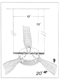
Il convient en premier lieu d'effectuer une pesée précise de l'hélice. Ensuite on la suspend au système mis en place, puis on la laisse se stabiliser. Puis on l'écarte de 20° de l'axe et on la lâche. On chronomètre le temps mis par l’hélice pour effectuer 30 oscillations complètes.
On reporte le poids de l'hélice en abscisse sur le graphique et on observe l’intersection de la droite horizontale issue de ce point avec l’oblique correspondant à la période la plus proche de celle mesurée. De ce point, on abaisse une verticale sur l’axe des ordonnées pour obtenir le moment d’inertie.
Grâce à leur grande légèreté, les hélices E-Props respectent largement les limitations de moment d'inertie préconisées par chaque motoriste.

En 2016, ce colloque traitant de tous les thèmes relatifs à la conception, à la structure, à l’aérodynamique, à la propulsion, à l’utilisation et au pilotage des avions légers s'est déroulé les vendredi 10 et samedi 11 juin 2016.
Jérémie Buiatti, concepteur des hélices E-PROPS, s'est intéressé à ce qui se passe entre le moteur et l'hélice.
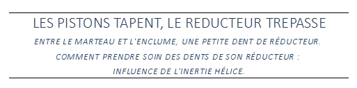
ARTICLE "Les pistons tapent, le réducteur trépasse" (en PDF)
Ils réalisent les calculs théoriques, la modélisation, la mise au point des prototypes, puis les expérimentations au banc au sol et en vol. Ils ont une grande expérience, reconnue par leurs pairs, et sont sollicités régulièrement pour intervenir lors de conférences et colloques spécialisés.
Quelques informations sur les travaux du bureau d'études E-PROPS :
1 - Conception / Design hélices
2 - Méthode d'optimisation d'hélices aéronautiques
3 - Hélices de 3ème génération
4 - E-PROPS : essais sol
5 - Bancs d'essais
6 - Propulsion : un peu de théorie
7 - Hélice et Moment d'Inertie
8 - Influence de l'inertie hélice
1 - Conception / Design hélices
Le bureau d'études E-PROPS élabore les spécifications et le cahier des charges de chaque hélice en prenant en compte :- les caractéristiques du moteur thermique ou électrique (puissance, couple, régimes)
- l'appareil qui va être équipé avec ce groupe motopropulseur optimisé : configuration tractive ou propulsive, caractéristiques aérodynamiques, interactions ailes / fuselage...
- les performances souhaitées de l'appareil
- les conditions d'utilisation de l'appareil et de son groupe motopropulseur
Les hélices E-PROPS sont étudiées pour être les plus légères possibles, très solides, permettant d'obtenir un excellent rendement et en tentant de générer peu de nuisances sonores.
2 - Méthode d'optimisation d'hélices aéronautiques
Optimiser une hélice pour un moteur donné sur un appareil existant est un problème complexe car :- la cellule et le moteur étant fixés, la vitesse de vol, le régime de rotation et la puissance sont imposés;
- le diamètre est souvent restreint par la géométrie de l’appareil. Et si par chance il ne l’est pas, c’est la vitesse périphérique et les problèmes supersoniques qui vont limiter le diamètre.
Le diamètre et la puissance du moteur fixent le rendement propulsif, c'est-à-dire la limite supérieure absolue du rendement possible de l’hélice. Ensuite, c'est au concepteur de l'hélice de se rapprocher de ce rendement.
Comme paramètres d’optimisation, il reste donc :
- le nombre de pales
- la répartition de traction sur l’envergure de la pale
- la répartition de corde
- la répartition de pas
- l’évolution de profils
Augmenter le nombre de pales permet de réduire la portance de chaque pale, et donc de réduire la traînée induite de chaque pale. Mais à corde constante, cela augmente la traînée de frottement. Et si l’on réduit la corde, la chute des Reynolds dégrade l’aérodynamique des profils, sans compter les problèmes de tenue mécanique.
La recherche d’une répartition de traction optimum doit prendre en compte les effets de celle-ci sur la traînée induite des pales. En effet, le saumon ne peut pas générer une forte portance sans causer une énorme traînée induite.
L’optimisation en corde cherche à ce que chaque profil travaille à finesse maximum, sans négliger les effets de la variation des Reynolds, et en vérifiant l’adaptation des profils à leurs conditions de fonctionnement en CZ, en Reynolds et en Mach.
La répartition de pas sert de variable d’ajustement pour maintenir chaque profil à son coefficient de portance optimum en vue d’obtenir la répartition de traction choisie avec une répartition de corde et de profil optimisée.
De par sa complexité, la conception d’une hélice est un procédé itératif : chaque modification influe sur les autres paramètres.
3 - Hélices de 3ème génération
Depuis les débuts de l'aviation, les hélices n'ont pas cessé d'évoluer.
On distingue à ce jour trois périodes principales :
1ère génération
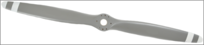
La 1ère génération d'hélices pour l'aviation légère, c'étaient les hélices en bois ou en métal, sorties dans les années 1940 - 1950, adaptées plus ou moins bien aux moteurs en prise directe de leur époque (Continental, Lycoming, Volkswagen...). Hélices à pas fixe, le plus souvent certifiées. Pour avoir un rendement un peu meilleur, la seule solution était à l'époque d'utiliser quelques rares hélices à pas variable, lourdes et chères.2ème génération
Dans les années 1980 - 1990, l'émergence du mouvement ULM a permis de sortir du principe de certification dans de nombreux pays. On a vu arriver sur le marché des hélices en matériaux composites, plus légères, prévues pour les moteurs réductés, et surtout à pas réglable au sol, ce qui permettait d'adapter l'hélice au moteur considéré. Le principe du pas réglable au sol a été une avancée considérable pour l'aviation de loisir.3ème génération
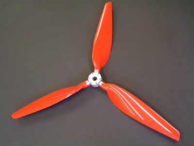
Les années 2000 - 2010 voient apparaître la 3ème génération d'hélices. Grâce aux performances mécaniques du carbone, de nouveaux designs aérodynamiques deviennent possibles : profils creux, cordes étroites, très grands diamètres, positionnement inédit des pales... Les études par modélisation numérique permettent d'optimiser les performances de l'hélice sur toute la plage de vitesse de l'aéronef. On obtient ainsi des hélices comme les E-PROPS, à pas réglable au sol (fixe pendant le vol) ayant une traction optimisée, avec des performances proches de celles d'hélices à pas variable en vol. On n'a plus à choisir entre les performances au décollage et celles en croisière.Les gains de performances sont importants. Ces hélices dites "de 3ème génération" (comme les E-PROPS) remplacent peu à peu toutes les hélices d'ancienne génération, ce qui permet d'accroître les performances et la sécurité.
Les constantes avancées des technologies, des outils de conception et de tests laissent envisager dans les prochaines années de nouveaux progrès sur cet équipement essentiel de l'aéronef qu'est l'hélice.
4 - E-PROPS : essais sol
Tous les modèles d'hélices E-PROPS sont soumis à de nombreux essais pour s'assurer de leurs performances, de leur tenue mécanique en fonctionnement et de leur adéquation aux moteurs pour lesquels ils sont conçus. En effet, pour chaque nouveau modèle, il est nécessaire de confronter les calculs et la réalité physique.Des essais ont également été menés en soufflerie, lors de développements d'E-PROPS spécifiques pour les drones. Ces essais sont confidentiels et ne peuvent pas faire l'objet de communications. Ils ont permis de vérifier de nombreuses hypothèses et d'enrichir le logiciel LUKY.
Exemple :
VIDEO : Campagne d'essais : hélices E-PROPS à pas réglable pour moteurs de 50 à 115 kW
Campagne d'essais : hélices E-PROPS à pas réglable pour moteurs de 50 à 115 kW. Tests de traction, flexion et torsion.
Des pièces carbone aussi solides que l'arbre du réducteur Rotax !
5 - Bancs d'essais
E-PROPS a développé de nombreux bancs d'essais et de mesures, par exemple :- Banc d'essais instrumenté hélices pour tests en fonctionnement, avec système de mesure de traction. Un moteur électrique permet de faire des essais comparatifs de bruit d'hélices.
- Banc d'essais en fatigue. Ce banc permet de solliciter l'hélice en carbone par flexion alternée, pour reproduire le couple moteur et ainsi démontrer un potentiel vérifié de l'ensemble moyeu - pale.
- Banc d'essais de traction mécanique : vérin hydraulique 40 tonnes pour les essais de traction et de compression des pales et des moyeux. Ensemble instrumenté pour enregistrement des données.
En 2015, l'équipe E-PROPS a acheté un ULM SKYRANGER équipé d’un Rotax 912S 100 cv.
Cet investissement a été réalisé pour poursuivre le développement de la gamme d’hélices pour ULM / Avions.
Cet appareil possède une structure "tubes et toile" très simple, qui facilité le montage d'instruments innovants d’enregistrement des paramètres de l'hélice dans toutes les phases de vol.
Le DAU (Data Acquisition System) appelé MERLIN, conçu et fabriqué par le bureau d'études E-PROPS, permet d'obtenir de nombreux paramètres à chaque instant du vol : traction hélice, couple hélice, T°, pressions statique et dynamique, régime moteur, pression et T° d'admission, valeurs d'incidence et de dérapage, etc.
Un système complexe de différents types de capteurs et jauges de contraintes est intégré dans le moyeu de l'hélice, sur les pieds de pale, ainsi qu'à différents endroits stratégiques de l'aéronef. Pendant le vol, des milliers de mesures sont envoyées en temps réel par liaison Bluetooth à un ordinateur situé dans l'appareil, ainsi qu'à un afficheur qui permet au pilote d'affiner son pilotage en fonction des paramètres demandés et obtenus.
Les résultats obtenus sont plus précis et proches de la réalité que des essais en soufflerie, et ils sont obtenus dans un temps très court (le temps du vol). Pour obtenir le même nombre de données, il faudrait des années de campagnes d'essais dans des souffleries. En outre, rien ne remplace les conditions réelles de vol.
Les données sont ensuite intégrées au logiciel LUKY .
Cet ensemble de moyens d'essais et d'analyse (ULM + DAU + logiciel) apporte une aide novatrice et précieuse aux ingénieurs du bureau d'études E-PROPS.
6 - Propulsion : un peu de théorie
Pour comprendre le fonctionnement d’une hélice, il est plus simple de partir de l’écoulement global en lui appliquant les lois issues de la physique expérimentale, afin d'essayer de ne pas masquer un phénomène simple derrière plusieurs équations trigonométriques.Tout d'abord, la troisième loi de Newton (ou principe des actions réciproques) indique que :
"Tout corps A exerçant une force sur un corps B subit une force d'intensité égale, de même direction mais de sens opposé, exercée par le corps B".
Cette loi se résume par le principe : " Action = Réaction".
Ceci signifie que si l’on souhaite que notre hélice "A" profite d’une force vers l’avant, il va falloir qu’en retour elle applique sur "B" une force vers l’arrière. Dans le cas de la propulsion aérienne, il n’y a qu’un "B" possible : c'est l’air traversant le disque balayé par les pales.
Il s’agit en fait non d’une masse proprement dite, mais d’un débit massique, produit de la surface du disque d’hélice, de la vitesse et du flux et de la masse volumique.
Pour appliquer une force sur le débit massique d’air, les pales se comportent comme des ailes. Leur profil aérodynamique leur permet d’appliquer des efforts de portance sur le flux d’air. L’hélice applique donc une force sur un flux d’air, ce qui a pour conséquent de modifier la vitesse du flux d’air.
La différence de vitesse entre l’amont de l’hélice et l’aval se calcule ainsi :
Différence Vitesse (amont/aval) = Traction / Débit Massique
DV = T / dm
Équation issue de la 2ème Loi de Newton F = d(m.v)/dt
Cette variation de vitesse induite par la traction s’applique pour moitié en amont de l’hélice et pour moitié en aval (comme le démontre la relation de Froude).
Le débit massique du flux d’air dans lequel travaille l’hélice est donc : Dm = mvo x Sdisque x (Vvol + DV/2)
Où :
- mvo = masse volumique du fluide (kg/m^3)
- Sdisque = surface du disque balayer par l’hélice (m²)
- Vvol = vitesse de vol
On a donc un système d’équation permettant de calculer la différence entre la vitesse en amont de l’hélice et la vitesse en aval, ainsi que le débit massique. Si l’on fait quelques calculs de puissance autour du fonctionnement de notre hélice, on obtient :
- La puissance utile fournie par l’hélice à l’avion : Pu = Traction x Vvol
- La puissance absorbée par le phénomène propulsif : Pa = Traction x (Vvol + DV/2)
Ce qui donne le rendement propulsif : rp = Pu / Pa
=> Le rendement propulsif fixe une limite absolue vers laquelle toute conception d’hélice devrait tendre
Comme le rendement propulsif fixe la limite supérieure de rendement d’une hélice, le choix d'une hélice de petit diamètre par le concepteur d’un aéronef aboutira à de piètres performances. Ceci est d'autant plus vrai que la vitesse de vol sera faible.
Si le nombre de pales peut permettre de réduire la perte de performance (nous verrons comment un peu plus loin), cela ne permet en aucun cas de retrouver les performances d’un diamètre adapté.
Si le concepteur d’hélices ne peut pas outrepasser les pertes liées au phénomène propulsif, il doit cependant ne pas les dégrader par une mauvaise répartition de la traction sur le disque d’hélice. Et doit donc choisir une répartition de pas, de corde et de profil permettant une répartition de charge optimum.
Malheureusement, il existe d’autres sources de perte énergétique : les pertes liées à la traînée des pales.
En effet, les pales se comportent comme des ailes et génèrent portance et traînée. Cette traînée se décompose en deux parties : la traînée de frottement et la traînée induite par la portance.
A/ La traînée de frottement sur les profils de la pale
Elle est définie ainsi :Traînée = 0.5 x mvo x S x CX x V²
Le cas de la pale est plus complexe que celui de l’aile, car la vitesse est variable :
- au pied de pale :
Vitesse faible et corde petite donnent un nombre de Reynolds ridicule dégradant beaucoup les caractéristiques du profil (CX important et CZ max faible).
- en bout de pale :
Vitesse très grande et corde très petite, le nombre de Reynolds reste petit.
Mais la vitesse étant proche de celle du son, le nombre de Mach est important.
Le Mach important dégrade les caractéristiques du profil. Un petit défaut de courbure, d’incidence, et une zone d’écoulement risque de passer supersonique, générant du bruit et dégradant les performances.
B/ La traînée induite par la portance
L'aile a une envergure finie, et par conséquent la portance s’accompagne de traînée induite.La modélisation de cette traînée induite est délicate, car, contrairement au cas de l’aile, la vitesse est variable le long de la pale.
Pour ce point précis, les chercheurs d'E-PROPS n'ont pas trouvé pas de méthode satisfaisante dans les publications spécialisées ni auprès de laboratoires. L’équipe a donc développé une méthode de calcul originale et efficace, mais un peu gourmande en calcul. Les calculs itératifs de définition des effets induits pour les pales représentent 90% du temps de calcul nécessaire à la modélisation complète de l’écoulement.
Nous avons vu ici en quelques mots quelles étaient les causes de perte énergétique de la propulsion par hélice, sans toutefois entrer dans les détails trigonométriques de la chose : ces détails ne représentent un réel intérêt que pour l’hélicier.
7 - Hélice et Moment d'Inertie
L’inertie d’un objet est sa faculté de résister à une variation de vitesse. L’inertie est directement liée à la masse de l’objet, et se mesure en kg.Pour des objets en rotation, la masse n’est pas une donnée suffisante. On a associé la masse de l’objet à sa distance par rapport à l’axe de rotation afin de pouvoir comparer la capacité de résistance à une variation de vitesse angulaire. Il s’agit du moment d’inertie, qui se mesure en kg.cm²
Le moment d'inertie est une donnée très importante pour les hélices.
En effet, les moteurs aéronautiques sont le plus souvent des moteurs à pistons. Le vilebrequin subit une poussée de la bielle à chaque tour en 2 temps, et tous les deux tours en 4 temps. Le vilebrequin est accéléré pendant un demi-tour, et est freiné pendant le reste du cycle. C’est l’inertie de tout l’ensemble rotatif qui va permettre d'assurer la remontée des pistons et la régularisation de la rotation.
L’hélice constitue le plus gros volant d’inertie. Si elle est entraînée par un réducteur (pour les moteurs réductés), les pointes de couple moteur seront encaissées par le réducteur. Si elle est reliée directement sur le vilebrequin (pour les moteurs en prise directe), celui-ci subira tous les efforts. Les efforts se transmettent en outre à travers tout le système : les vilebrequins des moteurs réductés peuvent également souffrir si le moment d'inertie de l'hélice est trop élevé (voir paragraphe 8). Et les vis de fixation de l’hélice sont soumises aux mêmes efforts.
L'utilisation d'une hélice possédant un moment d'inertie supérieur aux valeurs indiquées par le motoriste va entraîner une diminution de la longévité, voire même une rupture des éléments du réducteur, du vilebrequin ou des vis de fixation de l'hélice.
C'est pourquoi les motoristes indiquent les valeurs maximales de moment d'inertie des hélices qui peuvent être montées sur leurs moteurs.
Exemple pour les moteurs ROTAX, voir le document Rotax : Max. Moment of Inertia Rotax 912 Serie
Par exemple :
- Rotax 582 réducteurs A & B : 3000 kg.cm²
- Rotax 582 réducteurs C & E : 6000 kg.cm²
- Rotax 912, 912S, 912iS, 914 : minimum 1500 kg.cm² / maximum 6000 kg.cm²
- Rotax 915iS : minimum 1500 kg.cm² / maximum 7500 kg.cm²
- Jabiru 2200 : 3000 kg.cm²
A noter : en cas de problèmes liés à l'utilisation d'une hélice inadaptée, au moment d'inertie trop élevé, les motoristes refusent toute garantie.
Les moments d'inertie des hélices E-Props sont calculés lors de la conception à l'aide du logiciel LUKY. Ils sont en outre vérifiés par mesure pour chacun des modèles d'hélices.
Quelques exemples :
- tripale tractive dia 160 cm : 2.400 kg.cm²
- tripale tractive dia 180 cm : 3.800 kg.cm²
- tripale propulsive dia 170 cm : 2.700 kg.cm²
- quadripale propulsive dia 172 cm : 3.600 kg.cm²
- 6-pales propulsive dia 170 cm : 4.000 kg.cm²
Il convient de connaître le moment d'inertie de son hélice et de bien vérifier qu'il respecte les limitations du motoriste.
MESURE DU MOMENT D'INERTIE DE L'HELICE
Le principe consiste à mesurer la période d’un pendule à axe horizontal, avec un rappel constitué par le poids de l’hélice.Le motoriste ROTAX a édité une notice permettant de mesurer le moment d'inertie des hélices =>
Document Technique ROTAX ref SI11UL91E : Mesure du Moment d'Inertie Hélice
Il convient en premier lieu d'effectuer une pesée précise de l'hélice. Ensuite on la suspend au système mis en place, puis on la laisse se stabiliser. Puis on l'écarte de 20° de l'axe et on la lâche. On chronomètre le temps mis par l’hélice pour effectuer 30 oscillations complètes.
On reporte le poids de l'hélice en abscisse sur le graphique et on observe l’intersection de la droite horizontale issue de ce point avec l’oblique correspondant à la période la plus proche de celle mesurée. De ce point, on abaisse une verticale sur l’axe des ordonnées pour obtenir le moment d’inertie.
Grâce à leur grande légèreté, les hélices E-Props respectent largement les limitations de moment d'inertie préconisées par chaque motoriste.
8 - Influence de l'inertie hélice
L’association INTER ACTION (Association de Sauvetage Créatif du Savoir Aérotechnique), l’IUT de CACHAN et l’association AERODYNE (Association d’Etudes & Réalisations en Optimisation Dynamique & Energétique) organisent tous les 5 ans un colloque sur l’aéronautique légère à l’IUT de Cachan.
Jérémie Buiatti, concepteur des hélices E-PROPS, s'est intéressé à ce qui se passe entre le moteur et l'hélice.
ARTICLE "Les pistons tapent, le réducteur trépasse" (en PDF)